concretesubmarine.com/ FORUM

Members Login
Username 
 
Password 
    Remember Me  
Post Info TOPIC: concrete pressure vessel


Veteran Member

Status: Offline
Posts: 86
Date:
concrete pressure vessel
Permalink   


Concrete Floating Structures

Surface Floating Concepts:

The axes of ocean colonization / floating real estate building lots on the water / Plate Seastead - Plate Floating Element for Ocean Colonization / Catamaran Concrete Floating Elements - Base for Ocean Living / Floating Concrete Breakwater Marina / Ocean colonization how to get there / Ramform ship island as ocean base mobile stable scaleable / small honeycomb floating concrete structures in cartagena / Seabreaks for dampening colossal ocean waves / Ocean colonization technology / Ocean colonization company / Oustanding floating concrete structures / ocean colonization general considerations / Interesting projects for ocean colonization / Aquaculture, business, trade, mininig, energy, salvage, making money afloat /

Submerged Concepts:

The captain nemo float out - seasteading / Sub movement finished - Submarine Yacht / Is submarine living space expensive? / concrete pressure vessel / Concrete submarine project / submarine yacht / concrete submarine yacht supporter club / Submerged living space bubble concept basics / Exotic Submerged Bubble Hotel / sea orbiter / Current Turbine Concrete Hull /


--------------------------------------------------------------------------------------------------------------------------------------------------------

the problem would be if you ran aground at high tide in the first place--this is most likely the time a submariner will travel into shallower areas. if  all there is is low tide--it might be a while to get the sub off...if ever...why not use a slightly lighter sub--ballasted with enough water to raise it a few more inches then if it gets stranded--you can release?


__________________
Great spirits have always encountered violent opposition from mediocre minds A. Einstien


Newbie

Status: Offline
Posts: 1
Date:
Permalink   
 

Hallo everybudy
I must say that you ingnited my imagination like nothing else.
espacialy you will ,your work is incredable (to say the least).
I consider the oceans the last great adventure before going
to space (allways thoght that the astronauts must be submarine commanders).

For my personal submarine project I intend to go a diferent way.
a fast deep scaut vessel. the idea goes like this :take an ROV with all the gadgets you can have.
now put yuorself inside without the need for support ship and there you have it.

the concept of the concrete pressure hull is very reasonable and aese to do
specialy for the size I have in mind, 7~8m. that is apressure hul of 2m diameter
for 2 oceonauts .

This idea is still on my drawing board and there is so much information onlie
that I must study. I'll keep you posted.

Will ,many thanks.


__________________


Guru

Status: Offline
Posts: 11015
Date:
Permalink   
 

samtor, thanks for your kind words. The deepsea vessel that can operate without support ship is a tool that is absolutly necessary if you consider that the daily operation cost of a support ship are around 80.000 USD / day.
So if you loose 70% of your expedition days to bad weather (as usual in such expeditions) the cost of deep sea investigation is just ridicoulusly high. This explains why we know more about the far side of the moon than about the deep sea of our own planet. (see TED talk Bob Ballard)

 
You might want to consider that if you have a pressure sphere of only 2 m you can not stay inside such a limited room for longer than a few hours. This limits the independence of the vessel you need a mothership where you can transfer the crew to have a meal, a shower, a bed.

The question how big a living space bubble must be to allow a crew to stay there for a month (what would be a good expedition time) was investigated by Grumman in the Ben Franklin Project. The answer: a living space bubble of some 100 cubic meter size is sufficient to host a crew of 4 with all their needs during a month with no mayor technical, social, biological, medical, problem to expect in total insulation. This is valid in the same way for deep sea submarines as for space stations.

Based on this fact i would consider a minimum size for a completly long term independent sub some 100 tons of displacement.

Concrete spheres can be made to stand average ocean depth of 4000m - so this would allow to have a boat that can reach about 90% of the ocean botton - except the extreme depths of the ocean trenches.

I talked with Carsten Standfuss of the Euronaut project about building a deep sea salvalge submarine that could work indenpendent of a Mothership based on these principles. We agree that it would be a double hull boat with a series of spheres. Something along the lines of Deep Quest - just bigger.

cd-deepquest.jpg

The reason why we are not yet all over such a project is most of all that we could not yet find the right financial partners to pull it off.

Wil

concretesubmarine.com

[video=http://www.ted.com/talks/robert_ballard_on_exploring_the_oceans.html]


__________________


Veteran Member

Status: Offline
Posts: 86
Date:
Permalink   
 

yes this is a nice design...i wonder how woudl one go about makign a spherical mold?...two or three spheres in a exoshell would make nice pressure vessels indeed!! use connectors as in this one...in this case it makes me think--would it not be better to use three spheres instead of one cyclinder ? easy to make if you could get the mold right??..i dont know- something like what you do wil?...using a horizontal type of form system such a slip-form...then again--being in a ball might feel very small...not as nice as yours or the uc3 hulls long open space... do you have  a name for your sub yet wil??


Wil, when is Carsten launching his euronaut??? he went all out on that--spent lots of denarius on high tech gadgets..do you know what his specs are for submerged running??

what are yours wil??..curious..thx.


-- Edited by u-boatdreams on Sunday 2nd of October 2011 02:23:22 PM

__________________
Great spirits have always encountered violent opposition from mediocre minds A. Einstien


Veteran Member

Status: Offline
Posts: 86
Date:
Permalink   
 

will what would cause this?? im thinking salt?..but this is why im leary of using concrete...

those cracks are through the whole pillar...and its a standard mpa...


Attachments
__________________
Great spirits have always encountered violent opposition from mediocre minds A. Einstien


Guru

Status: Offline
Posts: 11015
Date:
Permalink   
 

dough, what is "better" depends on your needs and use of the boat.

The advantage of a single hull in blimp shape ( i would not go for cylinder due to streamlinening issues) is that you can use and design the interior like the interior of a business jet.

submarine-yacht-interior-design.jpg

The advantage of a 2 hull concept with spheres is in deeper dives, and storage capability for ROV and other equipment outside the pressure hull.

So if you go for yacht use the blimp will be the better concept, if for a salvage or investigation boat the sphere model will be a better choice.

If you check the video of the inside of a 200 ton boat ( see video)

.

You will find that having that space divided into 3 spheres you will have a "hamster cave ambient"  -  so i would implement segmented hulls perfered for boats with sufficient size so that one sphere can be taken as "room ambient" - about 5m diameter or so.

There are many ways to form a sphere in concrete,  the most important thing is that your forming method does respect the general ruling about concrete forms what concerns rebar distribution depth of spaces, access for compacting - those recommendations are there to assure that you get good final results.


-- Edited by admin on Saturday 20th of October 2018 11:50:08 PM

__________________


Guru

Status: Offline
Posts: 11015
Date:
salt damage in concrete
Permalink   


dough, i see you are very concerned about concrete in seawater. But trust me the experiences with floating concrete structures in the last decades made by oil / gas industy in the north sea has been EXCELLENT there is nothing to worry about.

Please check the following studies. (see here)

In short, damages on concrete structures - if any - happen in the "splash zone" this is where the structure experiments wet and dry cycles frequently. There is no damage if the structure is submerged permanently.

The foto of the bridge shows a damage caused probably by a combination of excessive use of thaw salt and poor concrete mix in the construction in first place.

Thaw salt damage and marine ambient are VERY different cases.

Cracks in concrete can have different origins and range from no problem to easy fix - to serious problem. Which is which needs differenciation. The most important thing is that the rebar does not get compromized.

The general picture is, if you see "appearant damage" by marine ambient on a "concrete structure" - you are probably looking at a structure made of faulty concrete mix  that never has been "concrete in in the sense of concrete engineering" in first place.

Well executed concrete stands in marine ambient for 200 years - with no sign of deterioration.

If the mix is faulty and the rebar inside starts to rust - what happens is, that the rust has 4 times the volume of the steel -  apart from tension resistance weakening due to steel loss, this process tears the piece apart from inside out due to the volume increase.

It makes little sense to think in "special covering" to avoid this - if the concrete mix is poor and faulty - the effects and damage will happen and be at plain sight in short time.

The good thing is - there is no hidden failure mode - if you mess it up you can see it clearly.


__________________


Veteran Member

Status: Offline
Posts: 86
Date:
RE: concrete pressure vessel
Permalink   


Good day wil...

i looked at all the vids many times--it keeps me inspired on my own project to watch them. lots of room especially if the weight brings it down to neutral or slightly pos.

I also read the paper you sent me on the platofrm troll legs. what i think is--and i dont know too much about it--is that the legs would be ballasted with water, cancelling out any pressure? so 300 meters is no pressure at all...when they pump it out the legs rise to 1 atm. so there really isnt any cycling going on??

correct me if i am mistaken..


what! no name for your masterpeice??

wil--im going to start my frames  very soon...ill drop you some pics of it...7 ft inner dia.

51.5 long scorpion class-your idea of a snorkel running is good--but not so long for me--maybe 10 ft or 12 ft (3.5 m) high...run under the waves...might go with an extension piece to add to it like a hose if weather gets rough...


__________________
Great spirits have always encountered violent opposition from mediocre minds A. Einstien


Guru

Status: Offline
Posts: 11015
Date:
Permalink   
 

Hello Dough,

The legs of Troll A are not filled with water.

2259264492_6e13082fac_o.jpg

They had to hold the full water pressure of 350m depth (at mating process). And they are now under 303m hydostatic pressure since decades. The engineers of the fotos are standing at the bottom of the legs.

troll-a.jpg . images?q=tbn:ANd9GcS1rpyIlD9ya-NUA7A55D5sTDMXIxODo9qSW_mxu889AP6VD4PBaKiiS9Qitg

The legs have 24 m diameter and 1 m wallthickness. The structure was built in a floating building site - ballast water is in the cells of the base structure.

Check the slip form method (no one shot pour).

3-alimak-hek.jpg


-- Edited by admin on Monday 3rd of October 2011 10:33:48 AM

__________________


Veteran Member

Status: Offline
Posts: 86
Date:
Permalink   
 

one meter thick??

wow- do the pre-stress the concrete? (reinforcing bars?)

id love to see those dropped to the mariana's trench and see what the implosion depth is..

the cylinder at 4700 ft was only 9 inches thick!


__________________
Great spirits have always encountered violent opposition from mediocre minds A. Einstien


Guru

Status: Offline
Posts: 11015
Date:
start frames
Permalink   


Dough, do i understand it right that you will have the lower part of the hull in fal to transport a light structure to the water - and then build with the method of "let form in place" on the water?


__________________


Veteran Member

Status: Offline
Posts: 86
Date:
RE: concrete pressure vessel
Permalink   


Hi wil, the idea is basically ferro-cement(either with or without the fal i have to do some destructive tests on both and a hyperbaric test on the fal)- my decision to use fal is through the use of it in my destructive tests- but its possible to use a sprayer for the fc method and make the job easy and penetrate the matrix better..and concrete is very cheap. about 1/4 the costs or FAL so two more test panels will be done this month i hope...if the fal is only slightly easier to work -we will use cement.


 i recently cut a slab from the destroyed FAL piece. intuitively i think it would be extremely strong and robust, 8000 psi compressive strength, and although it costs more the material can be worked more easily- we plan on using a divers hyperbaric chamber using 3/8th inch thick model to test destructive depth.


 so for the sub hull-I'd like to make a complete frame and weld longitudinal pieces of high tensile steel to form a mold. done the same as in FC.

 25 frames using 5/8ths rebar consisting of an inner ring(6.5 ft dia.) and the outer ring (7 ft dia)joined by 5/8th shaped v's...see picture... as you can see the walls are reinforced with rings as steel would be, making a higher safety margin..just in case...

i do not know how to make a mold or do slipforming for this shape of an object(teardrop) and since it is easier to pour the ballast id rather go this way...


the only other way is to pour in two halves but moving this and craning it is not viable..too costly..

doing it in chunks and joining might be too technical --but the big problem too is--

to make my sub scaled properly(to the exact replica-because this is a beautiful design to me) i cannot go to thicker walls than about 2 inches...if i did 6-8 inch walls using reinforced concrete conventionally, it would not scale properly... i.e. it would be 8.5 ft diameter and only 7 ft of inner diam..and it throws off the whole "look" of the scorpion class...

any ideas?


Attachments
__________________
Great spirits have always encountered violent opposition from mediocre minds A. Einstien


Guru

Status: Offline
Posts: 11015
Date:
Permalink   
 

u-boatdreams wrote:

Wil--in the paper- the scientific journal on the cylinder implosion. what is meant by a "cage" is this simply a layer of mesh?

would a 5 inch thick wall be too thin? i can go 6 inches tops for weight.


The rebar cage refers to rebar in horizontal and vertical bars so that they form a cage there is no mesh involved - the mesh in ferrocement boats has a different function- it is to hold the mix in place while it is curing.

You must see wall thickness in relation to the hull diameter - Troll A has a hull diameter of 24 m and a wall thickness of 1m so you have a ratio of 1:24 - my hulls have a ratio of around 1:13.3 - this means that at the same depth the concrete in TROLL A is about twice as stressed as in my hull - means also that my hulls can reach about twice the depth of Troll A.

Most important is that the thickness/diameter ratio is sufficient to rule out buckling as expected failure mode.  So i would recommend to not go below the 1:24 of Troll A .


-----------------------

The structure in the study below has a wall / diameter ratio of 1: 12,5 (24 cm wallthickness / 3 m diameter) very similar to my hulls.

-----------------------

Paper Number 3011-MS
Title OCEAN IMPLOSION TEST OF CONCRETE (SEACON) CYLINDRICAL STRUCTURE
Authors Roy S. Highberg and Harvey H. Haynes, Civil Engineering Laboratory
Source

Offshore Technology Conference, 2-5 May , Houston, Texas
Copyright 1977. Offshore Technology Conference
Language English
Preview ABSTRACT

An ocean implosion test was conducted on a pressure-resistant concrete cylindrical structure to obtain the depth at implosion. The structure was a reinforced concrete cylinder with hemispherical end caps, twenty feet (6.1 m) in overall length, ten feet (3.05 m) in outside diameter, and 9.5 inches (241 mm) in wall thickness. The structure was near-neutrally buoyant having a positive buoyancy of 12,000 pounds (5.4 Mg) for a hull displacement of 85,000 pounds (38.5 Mg). The implosion depth of the cylinder was 4700 feet (1430 m). A predicted implosion depth, using an empirical design equation based upon past test results, was 16 percent less than the actual implosion depth.

INTRODUCTION

A pressure-resistant, reinforced concrete hull was constructed in 1971 as part of a Seafloor Construction Experiment, SEACON I. The structure was placed on the seafloor at a depth of 600 feet (180 m) for 10 months. Figure 1 shows the SEACON I hull prior to its ocean emplacement. Since its retrieval in 1972, it has been located in the open air about 150 ft. (50 m) from the ocean. In the summer of 1976, the structure was returned to the ocean for an ultimate load test, that is, the structure was lowered into the ocean until implosion.

SPECIMEN DESCRIPTION

The cylindrical structure was assembled from three precast, reinforced concrete sections. The straight cylinder section, 10.1 feet (3080 mm) in outside diameter by 10 feet (3050 mm) in length by 9.5 inches (241 mm) in wall thickness, was fabricated by United Concrete Pipe Corporation. The concrete hemisphere end-closures, 10.1 feet (3080 mm) in outside diameter by 9.5 inches (241 mm) in wall thickness, were fabricated in-house. Tolerances on the sections conformed to concrete pipe standards of not to exceed to ±0.75 inch (19 mm) for the inside diameter or minus 0.5 inch (13 mm) for the wall thickness.

Steel reinforcement in the amount of 0.70% by area was used in both the axial and hoop direction. Reinforcing bars of 0.6 inch (15 mm) diameter were employed throughout the structure. A double circular reinforcement cage was fabricated for each precast section; the concrete cover on the outside and inside reinforcing cage was 1 inch (25 mm). For the cylinder section, hoop rebars had a spacing of 27.25 inches (692 nm) and 31.25 inches (794 mm) for the inside and outside cages respectively.

The hemispherical end-closures were bonded to the cylinder section with an epoxy adhesive, no other attachment besides the epoxy bond was employed (Figure 2). The gap between the mating surfaces of the hemisphere and the cylinder was less than 0.13 inch (3 mm) for 75% of the contact area. Prior to epoxy bonding, the concrete surfaces were prepared by sandblasting and washing with acetone.

---------------------------


__________________


Veteran Member

Status: Offline
Posts: 86
Date:
Permalink   
 

will- i get only 3.5 inches thick concrete  to go to troll depth and  7 inches at 1/12 ratio for 7 ft inner diameter hull.


actually the mesh does more than that--it distributes the loads, prevents buckling, and adds compressive strength...impact resistance 21 000 psi! at 5/8th thick.

the compressive strenght of 2 inch thick ferro cement is 10 000 psi! this would bring it down to near the bottom of the mariana's trench.

its very high strength to wieght ratio.

the only diff between it and conventional of course is weight..


__________________
Great spirits have always encountered violent opposition from mediocre minds A. Einstien


Guru

Status: Offline
Posts: 11015
Date:
Permalink   
 

Dough, i am not sure if i understand your project properly. Is the V shape supposed to hold external pressure or is it just a streamlined fairing in a 2 hull concept?

The steel itself in the tank collapsing in buckling failure has a pressure resistance of 40.000 psi -  this does not prevent the buckling failure at less than 10m depth.

What is important is not the compression strength of the material it is the compression strenght of the structure.

Anything that is not working in arch mode and fails in buckling will fail long long before the compressive strenght of the material is reached.

V or U frames can only hold a few meters of hydrostatic pressure - so you can use them for a pressure equalized fairing - but not for the pressure hull.


__________________


Veteran Member

Status: Offline
Posts: 86
Date:
Permalink   
 

sorry wil i wasnt clear on that--the rings with the v's or "truss type frames acting as spacers- do add strength this ring gets meshed then plastered over- adding strenght..they are used as floor supports later-- the inner ring is only a frame nothing more...


the hull itself is teardrop shape. identical to the,skipjack, scorpion etc. im using your idea of running submerged while using snorkel in rough weather.

the v"s are spacers for the two rings--i sent a pic to show in the last post--see pic and how the frames are made...

the hull will have successive changing diameter rings - the aft ring frame will be about 8 inches diameter- the biggest in the fwr'd 1/3rd of the teardrop shape will be about 7 ft diameter. same idea as boat frames but rings...

hope this clarifies things?  


-- Edited by u-boatdreams on Monday 3rd of October 2011 12:06:56 PM


-- Edited by u-boatdreams on Monday 3rd of October 2011 12:12:38 PM

Attachments
__________________
Great spirits have always encountered violent opposition from mediocre minds A. Einstien


Guru

Status: Offline
Posts: 11015
Date:
Permalink   
 

Frame design is for steel hulls - consider that the steel between the frames is in tension. The hull gets the aspect of a "hungry horse" under pressure, tensioning the skin over the ribbs.

Failure comes from welding failing under the tension load between frames - or frames failing under compression buckling out.

What comes first depends on the design (amount of ribbs) and quality of the welding. The predictibility of failure is difficult as it depends on many factors - being the compression strength of the material the less significative.

image003.jpg

FAL seems to be a material that can be built to the necessary properties. But you should be aware that you are completly on new ground when doing so.

So a prudent way to tackle the matter would be having the hull tested 1:3 unmanned to see if the concept works.

Also be aware of possible fatigue processes as they happen in steel.

To stay at the safe side you should repeate the 1:3 test dive frequently.


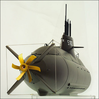
. navantia shipyard - steel frame construcction scorpene submarine -


__________________


Veteran Member

Status: Offline
Posts: 86
Date:
Permalink   
 

yes but the strenght of the fal, and the mesh is a composite...cannot buckle and if there was any chaance--the rings prevent it..maybe it will crack..but i doubt buckling as steel would..
haha- that looks like Peter !!! doing his kraka--ive never seen this pic before...

wil..were my calcs right? on the thickness? becuase it could be done at 5 inches thick and i could have it moved--it could even be done in a single pour...remember ill never go to 300 m unless the sub suffers some catastrophic failure..even though its a risk--its not likely itll ever go down that far especially in the great lakes--600 ft max depth maybe a bit more...although some places are 1000 ft..or 333 meters aprox. but few areas are that deep...


__________________
Great spirits have always encountered violent opposition from mediocre minds A. Einstien


Guru

Status: Offline
Posts: 11015
Date:
Permalink   
 

Dough, any material can buckle - buckling failure is not a material property it is a property of the hull geometry.

If you build in non uniform composite materials any calculation is in question so any strength calculation must be taken as a very rough and uncertain approximation - real world results can differ a lot from calculated ones. You can calculate non buckling concrete structures quite exactly and predict their failure point very well.

There are FE calculation methods for steel frame constructions - for ferrocement and FAL you are on completly unexplored ground and need to come up with valid calculations based on your own experiments.


__________________


Veteran Member

Status: Offline
Posts: 86
Date:
Permalink   
 

Wil, i was reading some old posts from the boatdesign site. (You know -idiots such as apex and rwatson..) anyway you made a great point-- those guy are all generalists in their arguments..

there are not real specialists out there..i guess this makes us specialists...one thing i was reading was about was how you keep the same ratio of concrete throughout the hull, i.e. the nose cone is less thick than the amidships...and the stern is less thick etc. would it be better to keep the concrete at the same thic
kness throughout? yes your ratios chnage but then again you add even more safety too...the ratios never go below you original...?? some of the arguments the others made had some good points and mostly i just saw rediculous pinada bashing(as one guy put it)...but may i ask why didnt you just tell them what concrete you use?? i, also very curious--i will eb using more sand and morter for fc than concrete... also i want to submit another polymer type concrete to show you here..let me know what you think of it as a FC type cement??
its called MG krete--

its a canadian product- and has 9500 psi compressive strength after 28 days...ive used it and it uses no water--its a green liquid you mix with the additives...it hardens fast like in about 25 minutes and it adheres to itself..very much like fal- its does cost about 50 dollars per bag. this makes it comparable to fal...
________________________________________
cost fal- 900 sq ft- 1.5 inches thick

fal about 8 units @ 385 ea. = 3080.00
mesh steel etc- 3000.00
resin-8 @500.00 = 4500.00 + shipping 1000.00
5500.00
total hull bare- 7 ft inner dia.

11 500 u.s.
____________________________________________
costs standard concrete-

4 cubic meters aprox... @ 200.00 ( sand and small aggregate mixed with fiberglass and new type of strengthener

900 sq ft aprox- 1.5 -2 inches thick.

= 800.00
3000.00 steel and mesh etc.
misc 1000.00

total
4800.00!! wow big difference.


http://www.imcotechnologies.com/canadian/datasheets/pdf/1260%20MG-Krete%20Part%20A.pdf

__________________
Great spirits have always encountered violent opposition from mediocre minds A. Einstien


Veteran Member

Status: Offline
Posts: 86
Date:
Permalink   
 

wouldnt youngs modulus work compared to steel or cement?


yes true uncharted territory but it has to start somewhere--

ill do a drop test first...if it holds at 600-700 ft--itll be safe at 200 my operation depth.


-- Edited by u-boatdreams on Tuesday 4th of October 2011 12:56:14 PM

__________________
Great spirits have always encountered violent opposition from mediocre minds A. Einstien


Guru

Status: Offline
Posts: 11015
Date:
Permalink   
 

"Buckling" is a failure mode characterized by a sudden failure of a structural member subjected to high compressive stresses, where the actual compressive stress at the point of failure is less than the ultimate compressive stresses that the material is capable of withstanding. This mode of failure is also described as failure due to elastic instability. Mathematical analysis of buckling makes use of an axial load eccentricity that introduces a moment, which does not form part of the primary forces to which the member is subjected.

buckled_column_medium.pngimages?q=tbn:ANd9GcQ0oQGtDN2d2vv5ZffH0-9peToCQqCjsdMFbpNTFIWsvq9_VQui8gimages?q=tbn:ANd9GcSkmAkVKFVVF8tFIDfOST7ZgJbDKG8WusBHNQoBF4jo9UKqKwfmLQ


__________________


Veteran Member

Status: Offline
Posts: 86
Date:
Permalink   
 

sure wil i undertsand that--when you speak of your subs as not worrying about buckling--taking the buckling element out because of the thickness--you are saying then i guess-that your hulls are built to a high saftey factor?

the problem using the catenary as an example is that forces under water act equally  at all points of the sub- compressing the hull at all points -this is why a sphere is the strongest shape...in those examples there is an unequal force apllied to just one block in the series--this creates a imbalance on the arch... this would not happen at depth--it would simply implode in all directions...


-- Edited by u-boatdreams on Tuesday 4th of October 2011 01:19:19 PM

__________________
Great spirits have always encountered violent opposition from mediocre minds A. Einstien


Guru

Status: Offline
Posts: 11015
Date:
Permalink   
 

Dough - the most important thing is that your hull is a inherently safe sistem with high safety factors. If you have a thick wall with buckling ruled out you get a very safe and predictable sistem with a big capacity to tolerate building errors and all kind of accidents - if you keep dives in scuba range you also maintain safety factors of 1:20 what is 10 times safer than what is usual in general civil engineering.

A framework hull gives you a structure where different forces operate in different parts of the hull - making it much harder to predict what will fail how and when. (is it the skin in tension, the frame in buckling, etc...)

The good news is there is no need to predict the failure exactly. As long as you test your finished hull and leave a 1:3 factor between test dive depth and operation depth you are fine and in a "acceptable safety range according to general engineering.

There may even be classification societies that will accept and certify a unmanned test dive in presence of an inspector as proove of safety without asking for anything else. (calcs, FE , inspections during build, and tousands of avoidable cost...)


__________________


Veteran Member

Status: Offline
Posts: 86
Date:
Permalink   
 

yea--its the only way ill feel safe--ill drop it..hopefully itll be ok...actually what you dont know is that by the time im done my sub i should have also finished my naval architecture diploma too..i am enrolled at the macnaughton school..there is some emphasis on FEA--

im guessing doing the drop is an expensive ticket..however--maybe i can certify it myself-if i have the qualifications by then?...who knows......if you were going to do a 5 inch thick hull wall would you just use a cage and maybe a layer of mesh?


__________________
Great spirits have always encountered violent opposition from mediocre minds A. Einstien


Guru

Status: Offline
Posts: 11015
Date:
Permalink   
 

videos what to expect - load cases submarine hull with external stiffeners, plating between 2 strong frames, plating without frames in buckling.


...

Last moments of USS Scorpion - watch the unexpected failure by "telescope" failure, FEA cylindrical vessel failing between stiffeners. / failure of cylindrical shell / non elastic failure with no buckling of a concrete sample

..

Note : as you see from the concrete sample compression test, you can expect a non buckling concrete hull to give you a "warning of overstress" in form of small pieces of material splitting away (with loud sound) long before the hull will actually fail completly and fatal - this "prewarning behavior under compression stress" is a important "aditional safety factor in a concrete sub hull.


__________________


Veteran Member

Status: Offline
Posts: 86
Date:
Permalink   
 

Wil--those would be extreme cases in a well built sub...one thing i learned was that when you have a pressure hull what you need to have is""stability" condition- fer-lite-concrete and steel all have good stability conditions...something called creep/rupture formations...

this is axially applied loads to the walls of the pressure vessel from the exterior-such as in the case of water pressure......ive been reading up on this a bit-

how did you make your prop?? i can size a prop for a boat but how do you size one properly for a sub--??


-- Edited by u-boatdreams on Friday 14th of October 2011 06:35:05 PM

__________________
Great spirits have always encountered violent opposition from mediocre minds A. Einstien


Veteran Member

Status: Offline
Posts: 86
Date:
Permalink   
 

creep buckling-

Buckling that may occur when a compressive load is maintained on a member over a long period, leading to creep which eventually reduces the member's bending stiffness.


Read more: http://www.answers.com/topic/creep-buckling#ixzz1aoHLccaT


http://dl.acm.org/citation.cfm?id=1351522


-- Edited by u-boatdreams on Friday 14th of October 2011 06:35:43 PM

__________________
Great spirits have always encountered violent opposition from mediocre minds A. Einstien


Veteran Member

Status: Offline
Posts: 86
Date:
Permalink   
 

http://www.youtube.com/watch?v=HLnV-fdf9kQ

prestressed concrete...


__________________
Great spirits have always encountered violent opposition from mediocre minds A. Einstien


Guru

Status: Offline
Posts: 11015
Date:
Permalink   
 

Dough, it is of essence that you understand in detail what kind kind of load case you will have on your hull, and derivated from that what kind of issues you have to look after.

The load case depends much on how your hull works . Is it working as a compressed shell, or is it working as a framework with a outer skin tensioned over a rib skeleton.

Once you have that clear you will know what kind of "critical issues", what are the material porperties you need / or not need / to look after.

Creep buckling is certainly a problem you look after if you build in materials that are known for displacements when under force (chewing gum, ice, glass, )

Concrete is not a material that needs a lot of concerns about creeping and its consequences in general. It is obvious that all the columns in a all those higrise buildings do hold thousands of tons of constant compression forces for many decades without any problems.

Prestressing is certainly a field that is interesting if you plan to have concrete under tension load - what prestressing does for you is keeping concrete that would otherwise be under tension load under compression load. The tipical case is a concrete bridge over columns the underside of the concrete beams would be in tension if not prestressed.

A all side equally compressed round hull as it is the case of a submarine hull under hydrostatic load is not a case where prestressing is a particular concern. On the other hand you might consider prestressing as part of the deal when you expect extreme hog and sagg forces on the hull as it happens in military submarines when underwater explosions are part of the package.

Prestressing also might be of use when you have a piece that can be under outer AND inner pressure - like a deco chamber.

Finally - all kind of odd effects may come up when you use a "exotic material" - this is why "stick to the proven" is certainly a good way to go.

Before you go for any "Design" have a engineer specialized in estimating and calculating forces on the hull when submerged to its test depth. This is a relative simple thing if you build a uniform buckling free round shell, and a highly complex one if you build a framework hull.

The general idea is that when you decide what test depth you will go for you do not exceed the limits the specific material is used in general engineering. You get a very clear picture about what is safe if you check norm tables. - they are designed to keep the engineering on the safe side.

It does matter little for which kind of engineering the norm table is designed, or if it is a european or US code. Materials do not know if they are part of a submarine or an airplane or a highrise building. The forces you can submit them are the same in all engineering disciplines and applications.

If you do not have subamrine specific norm tables at hand (because nobody developed such ) take tunnel and civil engineering norms to trace the limits of "safe material use" and your project will be just fine.


__________________


Veteran Member

Status: Offline
Posts: 86
Date:
Permalink   
 

and sizing the prop? how is this done?

__________________
Great spirits have always encountered violent opposition from mediocre minds A. Einstien


Guru

Status: Offline
Posts: 11015
Date:
Permalink   
 

The size of a ship propeller is limited by the space between keel and hull. In a sub (with a modern design) you don't have that limit. So you can make the propeller (called screw in submarine circles) much bigger.

E-prop14.gif. images?q=tbn:ANd9GcT7QdkBssLd0rzYn00J4xy9OKHr9xr6SQbHcxCma5VacDqjCFPR. .

The bigger and slow running a prop is, the higher is its efficiency. So what you should target for a sub is a very big very slow running propeller. Go for not more than one turn per second. One of the mayor advantages of big very slow running props is that you can actually picture the hydrodynamics going on there very easy with a couple of plastic strings and a camara.

The best way to do it is to build a big crude prop with a pitch that is equivalent to a heavy load prop for a displacement vessel ( like a deeploaded fishing boat) and do a first run with the boat over a pre measured distance.

The plastic strings give you a good picture how to change the form of the prop to "do it even better" you correct the turbulent zones with epoxy, fal, or a similar easy molding material, then do a second run that will be faster.

Optimizing the prop in several steps will lead you to a slow running high efficient prop optimized for your boat. - go for just 3-4 blades to simplyfy the task. Do not go for multi blade props with exotic shapes as you see them on military submarines. Those props are optimized for "low noise" which is of cero benefit for a yacht sub.

What you see on my sub in the picture is a crude preliminiary blade shape for a left turning slow running prop. The design of the hull allows to lift the prop to the surface by ballasting the nose of the boat for easy access to the prop for adaption, repair, and replacement. The prop is protected against collision by 4 skegs.

submarine-yacht.jpg. submarine_yacht_18m_200_ton.jpg


_________________________________________________________________________________

Thruster setup on a oceanic fish cage slow runnig large sized props - video

_________________________________________________________________________________


__________________


Veteran Member

Status: Offline
Posts: 86
Date:
Permalink   
 

Wil--thanks for that great explanaiton--on a boat i knew about prop aperture-however- there is a relationship to displacement and prop size..but of course on the sub you can use huge props..the skipjack had a 14 ft dia prop...

http://aqua-base.co.uk/concrete.html

CONCRETE
Life expectancy: up to 100 years or more
Condensation: none.
Initial cost: 7-8% more than steel, but greater economies of scale for multiple hulls.
Ongoing maintenance cost: much less than steel
Reduced down-time due to less frequent inspection
Excellent fatigue life
Good impact resistance
High mass moment of inertia and low centre of gravity means good station keeping behaviour and reduced motions
Slower thermal response/better insulation
Resistance to fatigue and crack propagation
STEEL
Life expectancy: up to 30 years
Condensation corrodes hull from inside
Initial cost: 7-8% less than concrete; traditional engineering and construction, fabrication in existing shipyards
Ongoing maintenance cost: much higher than concrete
Greater down-time due to more frequent inspection
More steel designers and fabricators are available


-- Edited by u-boatdreams on Tuesday 18th of October 2011 07:50:38 AM

__________________
Great spirits have always encountered violent opposition from mediocre minds A. Einstien


Guru

Status: Offline
Posts: 11015
Date:
Permalink   
 

What is written for surface boats does not apply very well to submarines as subs experience a different kind of hydrodynamic resistance, the absence of wave resistance can reduce the drag a factor 5 compared to a heavy surface boat of about the same size and displacement. Most of the military sub speed and prop data is classified as it is the core of sub stealth and performance capacity - so the best way to do it is taking a practical approach with a easy adaptable prop and figure it out by working out the turbulence zones on the prop and compare the speed of the boat in every round.

__________________


Guru

Status: Offline
Posts: 11015
Date:
Permalink   
 

Aqua-base is doing bases for floating housing - we have a discussion section about floating real estate and surface floating solutions (here).

As far as i can see from their website they do a kind of laminated ferro method.

Your FAL material and method is something similar.

Those building methods are very different from cast reinforced concrete building as done in classic engineering.

So their "compare to steel figures" are probably not valid for a submarine hull that is built in cast (their figure says 8% more expensive)

We calculate that a concrete hull as we have built it in our pilot projects is ten times less expensive than a compareable steel hull - just for the building of the hull.

It is important to compare apples with apples - so you should avoid to compare a light frame hull with a massive shell hull.

A massive shell has a destruction depth horizont of 1400m - a light steel frame hull will not stand half of this. Compare only hulls that are built for the same design depth and contain the same amount of material.

Also to make steel last 30 years you have to run a maintenance shedule that is extremly expensive - and it includes drydock stays that can be as expensive as building the hull in first place - a concrete hull is 100 years maintenance free and deterioration free - that marks a enourmous difference in favor of concrete.

So if you break it down in cost per year of service life a cost difference factor of at least 10 or more in favor of concrete emerges.

We have built hulls at a total project cost of 455 USD / ton of structure ready built.

Just the cost of steel structure is between 3000 and 5000 USD/ton.

This is already a factor 10 - just for building it.

If you calculate building cost plus maintenance cost divided by service years - you get something between well above factor 10 or multiples of factor 10 - depending on your calcs - for the cost difference calculation.


 Picture from aqua-base gallery section:

UnderConstruction1-lge.jpg


__________________


Veteran Member

Status: Offline
Posts: 86
Date:
Permalink   
 

yes- when i posted those steel vs concrete--it didnt make sense that it would be 7-8% more expensive than steel..i have costed out my porject and steel was about twice the costs...so not sure where they got that figure and how they calculated it Wil- do you see my plans in my avatar??...i thought of using a stucco sprayer over a simple mold and building up the layers of concrete to 6 inches thick - IF doing a conventional concrete sub..
in fact the costs of a simple 7 ft outside diameter pipe with end caps 8 inches thick for the concrete alone costs only about 2200.00 u.s. this is highly cost effectiveno condensation- fire resistant-maintenance free etc...


one thing too i should mention--to my understanding The Kraka, is no longer in service..it only lasted a few years because they built in steel and ran the cooling systems and some of the piping between the exo-shell and the pressure hull and in order to fix the rust, they would have had to remove the whole exoshell and rebuild it--not worth it i guess for Peter.

just to mention something funny--my name is spelled Doug..not dough..this is dough which means bread...in english..

want your opinion here:
to me that laminated Fc method looks strong--what about adapting that to conventional concrete..doing the hull in layers? over a form? i wonder if it would be better to do it that way as opposed to the standard FC way for a pressure hull?

__________________
Great spirits have always encountered violent opposition from mediocre minds A. Einstien


Guru

Status: Offline
Posts: 11015
Date:
Permalink   
 

The calculation steel vs concrete that aquabase is doing, may well be correct for their building method. If you check the picture above you see a lot of man with buckets of concrete and you see thin layers of fresh concrete. I assume that they have mesh wire sceletons that are filled with cement matrix - quality mesh wire is expensive, work is also expensive, the correct curing of thin layers of concrete is delicate, complicated, and therefore expensive too. So for THEIR specific building method 7-8% more expensive than steel might well apply.

I can see the plan of your sub. - looks nice. Do i see downlooking viewports?

Peter Madsdens Kraka is no longer in service,  Peter has biuilt a bigger sub yacht called Nautilus. (UC 3) - steel in marine conditions can be gone in a few months when the protection fails -  keeping protection by paint combined with anodic protection working is incredible expensive and a permanent struggle.

Like Peter many owners of steel ships decide to just let it go and not pay any longer. Especially a classic submarine littered with small spaces impossible to maintain, sandblast, and access is a preprogrammed quick victim for corrosion.


image003.jpgimages?q=tbn:ANd9GcTexWXxP4e9EkmGa5kqOHc1mFCt_rU2ms7pYG8d22HeSk2VeZWwb2lLlNKlCw


-- Edited by admin on Wednesday 19th of October 2011 08:10:05 AM

__________________


Veteran Member

Status: Offline
Posts: 86
Date:
Permalink   
 

Wil yes i had planned to put a viewport near the floor to guage depth if possible.. and to see below me to see fish, bottom, conditions, light etc...thanks for the compliment ..the sub is small but about as much space as a small room. have space for a bed, W.C. engine room, and a small galley--modelled after the inside of the UC3..Why would Peter build in steel after his problems with the kraka?? after all military was considering using concrete as pressure hulls in thier vessels- the idea was the sub would sit on the floor and fire missiles to boats on the surface--concrete%20sub%20diagram.jpg


1019682?AWSAccessKeyId=1XXJBWHKN0QBQS6TGPG2&Expires=1319673600&Signature=BW1v4JGqYjanBEP9g4%2B4%2B3LMyUU%3D


1019700?AWSAccessKeyId=1XXJBWHKN0QBQS6TGPG2&Expires=1319673600&Signature=SKVL0Yc%2B2tUNHQ7cpGliakNDclg%3D


-- Edited by u-boatdreams on Wednesday 19th of October 2011 09:41:15 AM

Attachments
__________________
Great spirits have always encountered violent opposition from mediocre minds A. Einstien


Guru

Status: Offline
Posts: 11015
Date:
Permalink   
 

There are many good reasons to build in steel - you can find know how for steel welding and building in every mechanic shop, you can find steelplating easy, you can get a hull together without building a form, you will have less questioning on the concept - steel hulls are a fairly common and widley understood by mainstream shipbuilding.

I don't see it as an error that Peter built in steel again, he is simply a steel man, educated in steel building skills, so he is making his subs with what he has on hand and is familiar with. There is nothing wrong about that.

Like with every material and technique there are up and downsides.

Wil


__________________


Veteran Member

Status: Offline
Posts: 86
Date:
Permalink   


here is a cost comparison analysis of the known viable alternatives for a submarine pressure hull...
sent to my business partner....
 

***four material alternatives***
 
for a pressure hull... using a 20-22 ft pressure hull. any design.


steel pipe method
--------------------------
cost analysis
steel pipe 20 ft x 6.5 ft dia.

need 12 4x 8 sheets 3/8ths thick @ 285.00 ea from my supplier = 3420.00
rolling costs @ 275.00 per sheet of 20 ft lenghts rolled and tacked = 1375.00
subtotal- 4795+ tax aprox 5500.00 plus shipping 400.00
= aprox 6000.00
weldment-700.00
subtotal 6700.00
 
plus end caps 1200.00 roughly
 
7900.00 for pressure hull.
 
 
conclusions:
 
not bad...cost effective- but labour intensive--we need extra tools and a lot of time welding up and then shipping the plate to be rolled i will classify this a tentatively non-viable method, due to the labour intensive nature and cost effectiveness. so this rules out a steel pressure hull unless we have one pre-fabricated at a cost of about
11 000.00- we must however keep  an option open for a cheap propane tank ??. unfortunatley steel is the easiest of all fabrication methods but its advantages are outclassed by its negatives as outlined above.
 
alternatives to steel
 
fer a lite
____________
cost analysis
FAL for 7 ft outside diam. = 7.5 units @ 385.00 each = 2887.00 plus shipping (600.00?)
resin 7.5 drums @ 700.00 ea. = 5250.00(based on reduced costs and shipping but this is underestimated most likely)
mesh and steel- 1500.00
 
total: 10 237.00
 
conclusions:
 
classified as non viable for the following reasons:
 
1. expensive. 2. labour intensive -far more than steel. 3. logistically time consuming. 4. some doubt as to the materials lasting strength under pressure.
 
Thus due to the high costs and the logistics of shipping, anaysis of the yield data for the product through proper means and intensity of labour and time involved to create a full hull with this..i have concluded -we are far better going with another method. even steel.


ferro-cement
 
2 inch thick concrete composite pressure hull
 
mesh 2500.00
cement- 800.00
tools- 1200.00
 
total -4500.00
 
conclusions:
 
Plausable...
this is a good financially viable way to build -however this is a time consuming process of building the armature. very labour intensive.
there is also the problem of this being an unproven/unknown method for a pressure hull. this means possible extensive testing which translates to time and money. furthermore--im worried about certain data which suggests impacts might be an issue if not done properly--only a test model would tell us..and then a drop test to determine if the hull could withstand such pressures...
because of the unknown factors i will classify this as plausable with moderately viable potential.
 
 
standard concrete pressure vessel
 
8-9 inch thick walls, 6.5- 7 ft dia, solid cast pipe.
 
mold- 800.00
concrete pour 2400.00
end caps- 500.00( with mold cost inc...)
 
total-3700.00
conclusions:
 
extremely viable.
It seems that this method-although extremely low tech, could prove to not only be the lowest cost, but also has proven data to back it up. Its also one of the fastest and has been previously pioneered by others. It is non labour intensive and can use common materials and labour. needs no special tools.
we would need to attach a steel overlay somehow but this could be worked through. perhaps using some type of bolt system. through hull and epoxied.
Also end capping might be a chore...lifting etc...however a mold is easily done and ive heard epoxy is used on prefab pipes for this--another option might be to use extenders; extensions of the rebar to create a monolithic mold for all parts- end caps and all. The mold is actually incorporated into the whole pour process. for instance a light ferro-cement outer and inner mold is done and used as the shell for the mold. steel overlay could be actually applied before the pour and welded to tabs...increasing strength and decreasing chances of blowouts.and giving a weldable surface for the outer free-flooding hull...furthermore- the weight of the hull is precisely what is needed to reduce ballast costs. we could even go 10 inch thick walls for added security...bulkheads of course would also be in concrete/or ferrocement adding a massive factor of safety...
further research will be needed to investigate the build process...and possible complications...
____________________________________


__________________
Great spirits have always encountered violent opposition from mediocre minds A. Einstien


Guru

Status: Offline
Posts: 11015
Date:
Project cost per ton of construcction
Permalink   


doug, i would be careful with "cost analysis" sent from somebody else, made for a project of unclear parameters.

The best way to do cost analysis is always to have clear that you need to think in "total project cost" - a project does never consist in 3 items you sum up and get a figure, a project always has "tousands of items" that sum up.

So the most important cost account is always the "other cost" account which contains the thousands of items that are not material cost. The most tricky part is to estimate the "other costs" globally correct.

One of the most simple ways to get there is to do a pilot project and have a dedicated project account so you get a analysis "money pumped into the project" versus "tons of construcction" comming out of the project.

I know that steel building in the United States is rated in 1000 - 5000 USD per ton of construcction.

So if you get a figure of 7.999 USD for your steel hull this can only be correct if the hull has a total weight somewhere between one and seven tons - if that is not so there are probably some major flaws in the calculation.

I also know from my pilot projects that i can crank out a ton of concrete construcction at USD 166 - so a factor 10 below steel standard project cost - but that is for south america.


__________________


Veteran Member

Status: Offline
Posts: 86
Date:
RE: concrete pressure vessel
Permalink   


good morning Wil--the cost analysis was mine..it appears that you are correct with concrete being the most viable and proven method ..which eliminates much of the guesswork...

the FAL is more costly than steel which surprised me when i did the anaysis. concrete done your way-or similar is the cheapest method and it looks like the best way since its so strong in compressive strength...


__________________
Great spirits have always encountered violent opposition from mediocre minds A. Einstien


Veteran Member

Status: Offline
Posts: 86
Date:
Permalink   
 

Wil--concrete here is 190.00 per cubic meter--or about 2.5 tons per 190.00!! one cubic meter is 5250 lbs!! yes the total cost of the build is the detail things -but ive factored all that..it has to start with the hull so this is the first place to get best potential for price...


__________________
Great spirits have always encountered violent opposition from mediocre minds A. Einstien


Guru

Status: Offline
Posts: 11015
Date:
Structural concrete building cost figures from precast plants
Permalink   


you should not take the figures from the concrete mix plant but project experience figures from engineering bureaus that contain concrete mix, plus the rebar works, plus concrete pumping, plus labor, plus forming, plus deforming, plus inherent costs that emegerge when the mix truck gets stuck in traffic and 20 workers stand around and wait for the concrete but still charge a workday etc... this "asociated project costs" can overpass the concrete cost as listed in the mix plant, several multiples depending on the complexity of the project.

Choose "asociated project cost figures" from a real world project that has a similar complexity level as your project. A good figure can be the cost of concrete engineered pieces from a precast facility. Get the weight of the piece (bridge piece, columns, stairs, ) and extract a dollar per ton figure, average over several pieces. Precast facilities have good "asociated cost figures" that are truley reflected in the sales figures of their products.

Keep in mind that precast plant figures will only apply to your project if your forming and work process is as efficient in tons per man and day as their process is. What they add to the prices for profit you will loose it due to less effiency due to lack of mass production.

Also streamline your process as far as you can. I get from your former comments that you plan to work with "craning and bonding of endcaps" - consider this a interuptive process "everybody waiting for the crane" - you may want to skip that kind of interuptive processes and try to get to a continous project flow.

The ideal is a man with a hand mixer producing concrete eight hours a day, seven day a week with no interrupt at all building up the hull in a contious process. You will be surprised what amount of tons built you can get that way.

And the best is you can see everyday if you are "in plan" or "off plan".


__________________


Veteran Member

Status: Offline
Posts: 86
Date:
concrete pressure vessel
Permalink   


Wil--what would stop me from doing a sort of method that is used for the tunnel sections you posted previously? the idea is this-- lay a ring mold on the ground. insert rebar. the ring mold would be 6 inches in width 4 ft high and 6 ft diameter. then you mix your own concrete, make the pour. when the concrete is hardened you make 4 more of the same --giving you a pressure vessel 7 ft outside dia. and 6 inside. you essentially "weld" these together using epoxy. pipes are inserted into the mold vertically so they can fit nicely together...then an adhesive epoxy is used. this would bond the sections together...tabs would protrude through the mold to allow a steel overlay for wleding up the exoshell in light gauge steel...

what r your thoughts on this?

of course you could carry this one step further wiht a continous pour but for me this is not feasible...


-- Edited by u-boatdreams on Wednesday 9th of November 2011 12:39:30 PM

Attachments
__________________
Great spirits have always encountered violent opposition from mediocre minds A. Einstien


Guru

Status: Offline
Posts: 11015
Date:
Permalink   
 

looks doable but somewhat overengineered and over complicated - why introduce epoxy bonding ? why introduce a steel exoshell ? - what is the benefit of complicating the building process ? where is the problem that needs to be solved with such complicated techniques?


Design of Offshore Concrete Structures / Construction of Marine and Offshore Structures, Third Edition / The Dock Manual: Designing/Building/Maintaining / Plasticity in Reinforced Concrete


__________________


Veteran Member

Status: Offline
Posts: 86
Date:
Permalink   
 

1. easier to build form

2. complicated formwork are avoided

3.good for limited space

4. quality can be controlled as concrete is easily accessed

5. allows cheap forms

6. not dealing with the weight fo heavy pipe


__________________
Great spirits have always encountered violent opposition from mediocre minds A. Einstien


Veteran Member

Status: Offline
Posts: 86
Date:
Permalink   
 

the exoshell makes it easy to work with fittings...appendages etc...

__________________
Great spirits have always encountered violent opposition from mediocre minds A. Einstien


Guru

Status: Offline
Posts: 11015
Date:
Permalink   
 

Why do you think that a complicated way to "make it easy to work with fittings" is a necessary design feature? If you look around in concrete civil engineering all kind of fittings are used without any hardship, and your local hardware store has dozends of suitable fittings and appendages on the shelf.

I would say that creating a suitable formwork and form things in place is much easier than doing the process you describe...but i may not have a adequate perception of the grade of complexity of your suggested method.

You would have to build something in both methods and then compare cost and workhours per ton structure built ...

My current numbers are 331 Euro per ton of structure built and i would say that you can form and work literally ANY shape at that cost (at least here in south america) ...

Reading List:

Basic Concrete Engineering for Builders with CDROM / Design of Concrete Structures / Strength Design for Reinforced - Concrete Hydraulic Structures Engineering Manual on CD / Design of Offshore Concrete Structures / Construction of Marine and Offshore Structures, Second Edition (Civil Engineering - Advisors) / The Dock Manual: Designing/Building/Maintaining / Theory and Design of Concrete Shells / Thin Shell Concrete Structures / design procedures of reinforced concrete shell structures (JGJT 22-98) / Understanding Structures / Concrete Planet: The Strange and Fascinating Story of the World's Most Common Man-made Material / Concrete Construction Manual (Construction Manuals (englisch)) / Large Wind Turbines: Design and Economics / Dynamics of Offshore Structures / Offshore Technology in Civil Engineering / Design of Offshore Concrete Structures / Concrete in the Marine Environment (Modern Concrete Technology)

-- Edited by admin on Thursday 15th of March 2012 09:55:31 PM

__________________


Veteran Member

Status: Offline
Posts: 86
Date:
Permalink   
 

Wil--how do you plan to set up your exhaust system??...im thinking i could draw raw water in a loop from my ballast tanks?
also my first test model is almost ready--ill be posting vids as it progresses...this is the first step- and already i think concrete is still the way to go--now i just need a mold. maybe doing it in sections isnt the right way but --what about a mold done in strip planks and a slip form which adjusts during a continuous pour? ie. a ring that has an adjustable cover on both ends of a ring which travels acrosss the cheap wooden mold? other than that i like the idea of using two differing diameter tubes. made of plywood or any cheap material then i  think its acually cheaper to stand the tube on end so the concrete compacts well-after all its only 22 ft high..it can poured in one shot...  i still like ferro cement but using my ultra strong fer- a- lite...either way the subs framing and mold process gets started in june --ill be doing test stages in the mean time over the winter..

pls explain --you need a dry exhaust right? for a snorkel?-..so where do you draw in your water intake or is it a closed system--to me it seems a radiator would be good for a sub engine since its a closed system and it needs no outer hull penetrations???


-- Edited by u-boatdreams on Wednesday 30th of November 2011 09:26:07 PM

Concrete Floating Structures

Surface Floating Concepts:

The axes of ocean colonization / floating real estate building lots on the water / Plate Seastead - Plate Floating Element for Ocean Colonization / Catamaran Concrete Floating Elements - Base for Ocean Living / Floating Concrete Breakwater Marina / Ocean colonization how to get there / Ramform ship island as ocean base mobile stable scaleable / small honeycomb floating concrete structures in cartagena / Seabreaks for dampening colossal ocean waves / Ocean colonization technology / Ocean colonization company / Oustanding floating concrete structures / ocean colonization general considerations / Interesting projects for ocean colonization / Aquaculture, business, trade, mininig, energy, salvage, making money afloat /

Submerged Concepts:

The captain nemo float out - seasteading / Sub movement finished - Submarine Yacht / Is submarine living space expensive? / concrete pressure vessel / Concrete submarine project / submarine yacht / concrete submarine yacht supporter club / Submerged living space bubble concept basics / Exotic Submerged Bubble Hotel / sea orbiter / Current Turbine Concrete Hull /


-- Edited by admin on Friday 31st of August 2012 01:10:17 AM

__________________
Great spirits have always encountered violent opposition from mediocre minds A. Einstien
«First  <  1 2 3 4  >  Last»  | Page of 4  sorted by
 
Quick Reply

Please log in to post quick replies.


Create your own FREE Forum
Report Abuse
Powered by ActiveBoard